SCANNING 4 - Seven SEGMENTs 8051


Wed Jan 07 2015, 03:30 pm
Hello,
I have worked of LCDs and Single Seven Segment .
Can Any Body Guide me How do I can Write Program on 4 - Seven SEGMENTs 0000 to 9999. with Timer Interrupt?
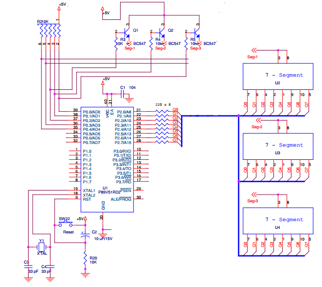
I have designed Circuit . My Schematic is As below.
P1.0 -> Select Segment First
P1.1 -> Select Segment Second
P1.2 -> Select Segment Third
P1.3 -> Select Segment Fourth
P3 -> Data Lines are connected to P3.(For Common Anode Seven Segment).
Thanks in Advance..
--
I have worked of LCDs and Single Seven Segment .
Can Any Body Guide me How do I can Write Program on 4 - Seven SEGMENTs 0000 to 9999. with Timer Interrupt?
I have designed Circuit . My Schematic is As below.
P1.0 -> Select Segment First
P1.1 -> Select Segment Second
P1.2 -> Select Segment Third
P1.3 -> Select Segment Fourth
P3 -> Data Lines are connected to P3.(For Common Anode Seven Segment).
Thanks in Advance..
--


Wed Jan 07 2015, 09:07 pm
"I have designed Circuit . My Schematic is As below."
Did you attach a Schematic ?
Check the list of file types we can accept.
There are several projects that use similar displays, have a look at them.
Did you attach a Schematic ?
Check the list of file types we can accept.
There are several projects that use similar displays, have a look at them.

Fri Jan 09 2015, 10:30 am
Zip and upload your schematic. Here is a sample source and simulation of 8 7-seg muxed display to get you started.
http://www.8051projects.net/t37289/8051-discussion-forum/source-code-circuit-diagram-for-8-seven-segment-fully-working.htm
http://www.8051projects.net/t37289/8051-discussion-forum/source-code-circuit-diagram-for-8-seven-segment-fully-working.htm
Wed Jan 28 2015, 10:31 am
Hello,
I have changed schematic according to this code for 3 - 7 Segment .
I have run this code on proteus working fine . But unable to see output on Actual Circuit 3 7 - Segments.
[ Circuit Diagram attached ]
Thanks in Advance ...
![]()
I have changed schematic according to this code for 3 - 7 Segment .
I have run this code on proteus working fine . But unable to see output on Actual Circuit 3 7 - Segments.
[ Circuit Diagram attached ]
Thanks in Advance ...
Thu Jan 29 2015, 06:36 am
The code in
http://www.8051projects.net/t37289/8051-discussion-forum/source-code-circuit-diagram-for-8-seven-segment-fully-working.htm
should be changed to..
unsigned char dis[8] = {0x01, 0x02, 0x04, 0x08, 0x10, 0x20, 0x40, 0x80};
unsigned char a[5]; // used for decoding the no.
Ports on the 89c51 can't handle much current, this is shared between 3 digits,
so will be disappointingly dim

Remove resistors R3,4 and 5.
Change the R2 pack to 1k
On the R2 pack, what do the connections on 5 and 6 do ?
Try a simple LED blink, test program to make sure your
hardware is working.
Thu Jan 29 2015, 11:58 am
Moreover I see the segment Anode is connected via transistor what about cathode?
Fri Jan 30 2015, 04:11 am
T he P89V51RD2 P1.5, P1.6, P1.7 has extra current drive features.
If you are using the P89V51RD2, connect Q1,Q2 and Q3 to these pins.
Pull up resistors will not be needed.
Edit the code to use these pins.
If you are using the P89V51RD2, connect Q1,Q2 and Q3 to these pins.
Pull up resistors will not be needed.
Edit the code to use these pins.
Wed Feb 04 2015, 10:51 am
I doubt if BC547 can provide enough emitter current to driver segments. Usually PNP transistors are used for such circuit. @Phil, correct me if I am wrong
Wed Feb 04 2015, 05:37 pm
Thanks all of you,
I have edited code and Tested Scanning Segment on my hardware. One More Question , for making counter 000 to 999.
I want to start counting 1's position from Right Most Position like 0 0 1 . But the counting start like 1 0 0 Left Most Position and after 9 _ _ and 1 0 0 and so on . Please Check the attached code and video .
Any suggestion...
Powered by e107 Forum System

Williamjaf
Tue Apr 16 2024, 12:25 pm

best_yyPa
Tue Apr 16 2024, 09:42 am

ErnestoExpop
Tue Apr 16 2024, 02:57 am

Jamesclepe
Mon Apr 15 2024, 11:10 am

Aliciaelora
Mon Apr 15 2024, 07:59 am

btaletvpcu
Mon Apr 15 2024, 04:36 am

UbvpwcTib
Mon Apr 15 2024, 03:13 am

AmyJow
Sun Apr 14 2024, 11:54 pm