ATmega8 Button Debounce Problem
Discussion in "AVR Discussion Forum" started by imranahmed Jan 4, 2014.


Sat Jan 04 2014, 02:06 am
Please let me know that I want to make button debounce program, ATmega8 at 8MHz on AVR Studio 4,the given program cannot generate delay for timer1 interrupt,
Please find what is the mistake I made with the code.
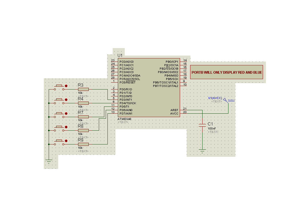
Also please find attachment.
![]()
Please find what is the mistake I made with the code.
Also please find attachment.
#include <avr/io.h>

#include <util/delay.h>

#include <avr/interrupt.h>

#include <inttypes.h>

#define Red 240
#define Yellow 232
//#define Blue
volatile char button_timer;
unsigned char button_pressed;


//timer 1 overflow ISR
ISR (TIMER1_COMPA_vect)

   {

	if (button_timer != 0){
	    button_timer--;
   }


}


void LED(void)
{
if(button_pressed==Red)
{
PORTB=0xFF;
_delay_ms(500);
PORTB=0x00;
_delay_ms(500);
}

else if(button_pressed==Yellow)
{
PORTB=0xFF;
_delay_ms(250);
PORTB=0x00;
_delay_ms(250);
}
}


int main(void)
{
    DDRD=0x07;
	PORTD=0xf8;
	DDRB=0xff;
	PORTB=0x00;
	button_pressed = 0;
	button_timer = 0;

	// set up timer 1
  	OCR1A = 16000;
    TIMSK = (1 << OCIE1A);
    //Set interrupt on compare match.

    TCCR1B = 0x0d;
    // set prescaler to 1024 and start the timer.
	sei();

	while(1)
	{


	if((button_timer == 0) && (PIND != 248))
	        {
			button_pressed = PIND;
			button_timer = 0;
			}
	else
			button_pressed = 248;
            LED();
	}

    return 0;
}


Mon Jan 06 2014, 01:32 am
Please let me know that I want to make button debounce program, ATmega8 at 8MHz on AVR Studio 4,the given program cannot generate delay for timer1 interrupt,
Please find what is the mistake I made with the code.
Also please find attachment.imranahmed
I don't think many of us want to wade through your code looking for errors.
Can you tell us what does work, and what does not.
Can you generate pulses using the timer ?
Can you see interrupts generated by the buttons ?
What does happen ?
What do expect to happen ?
Mon Jan 06 2014, 02:18 am
Dear ExperimenterUK,
I want to make digital voltmeter and using one button for display three phases voltage, one time press show Red phase second time press show Yellow phase and third time press show Blue phase voltages.
I was need button debounce program but this issue solved.Another issue occurs that is pins of PORTD (PD0,PD1,PD2) assign for 7-segment display but how to use other pins for another use?
Mon Jan 06 2014, 03:25 am
I'm glad your debounce problem is solved.
I don't use the ATmega8, but assume port control is similar to PICs.
In that case pins can be used independently, but exactly how is down to your compiler.
There will be functions to read and write a port (8 bits) at a time.
There will also be functions to read and write a single bit at a time.
Until an expert posts advice, I suggest you read your compiler help section looking for info
on the I/O functions it provides.
I/O can be complicated and compiler help sections are often not as helpful as they should be,
so read everything there is.
Also read the details in the chip data sheet.
Powered by e107 Forum System

ArktiTic
Sun May 05 2024, 07:06 pm

CesslasyNear
Sun May 05 2024, 02:58 pm

chimichmedic1204
Sun May 05 2024, 11:06 am

Jamiegob
Sun May 05 2024, 10:11 am

Gregoryjed
Sun May 05 2024, 10:02 am

Mariocax
Sun May 05 2024, 08:51 am

WilliamErync
Sun May 05 2024, 02:35 am

Danielnof
Sat May 04 2024, 11:12 pm